Canvey Railway and Model Engineering Club.
A METROPOLITAN TANK LOCOMOTIVE
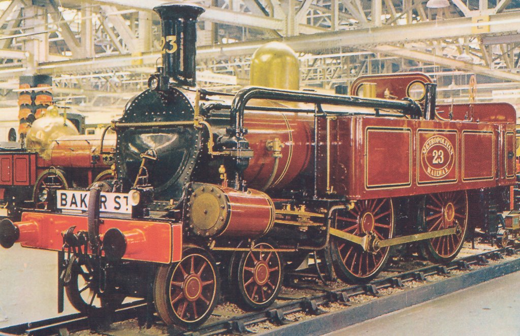
The full size locomotive to be modelled. The development of a Metropolitan Railway 4-4-0 tank engine in 71/4" gauge I have long had an interest in the Metropolitan Railway. It was the last of the London Underground to maintain some independence, and it did aspire to being a main line railway. Together with the Great Central it had dreams of joining the industrial heartland of Great Britain to the markets of Europe via a Channel Tunnel. When the first 3.75 miles of the railway were built, its aim was to relieve the horse drawn traffic congestion in central London. In the first three weeks it carried over 29,000 people – this was in 1863.
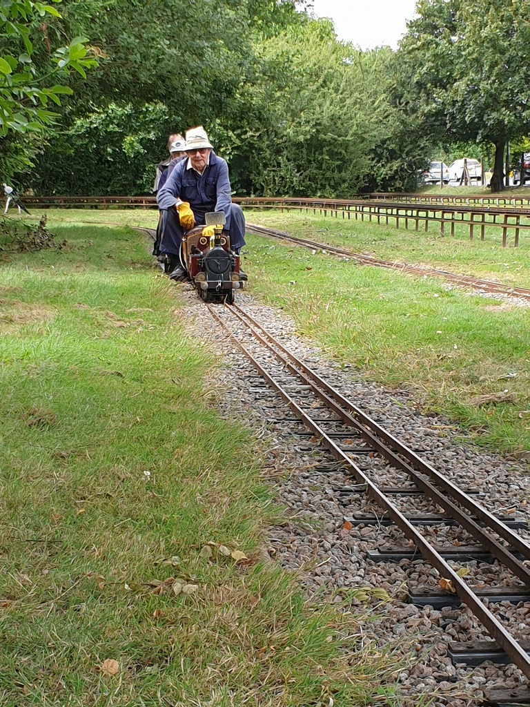
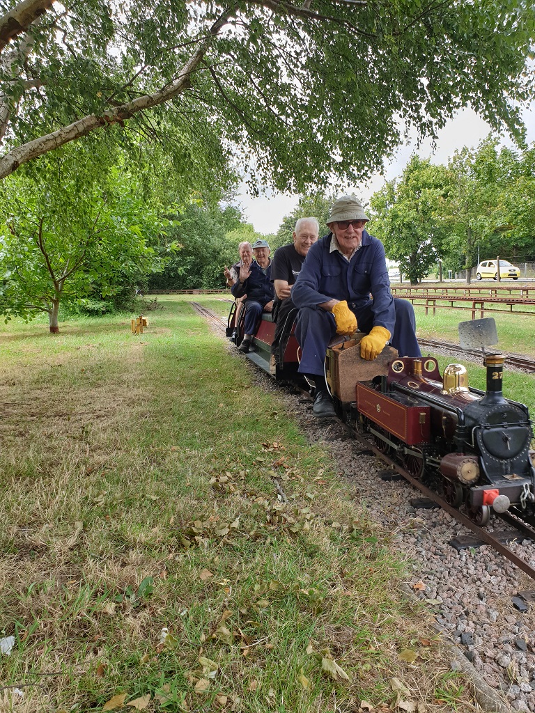
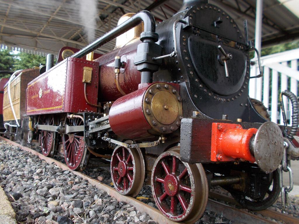
(Seen here having a load test after gaining her steam certificate July 2023)
The railway used locomotives and stock from other railways, but this was not very satisfactory and eventually in 1864 it decided to buy 18 4-4-0T locomotives built by Beyer Peacock of Manchester, later they expanded the fleet to 66. They lasted until 1906 when they were displaced by electrification. The specification for the locomotives required that they did not pollute the tunnels with smoke and steam. This was achieved by burning coke and condensing the exhaust steam in the side tanks. To keep a reasonable fire, the exhaust was allowed to draw-up the fire at open sections of the tunnels. After running for some time the water in the side tanks would become very hot. At various stations there were places where the water in the side tanks could be dumped and cold water refilled. The London Underground at that early period must have been a very unhealthy and unpleasant place.
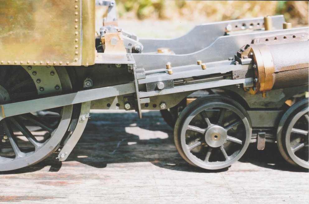
There is still an example of a Metropolitan Tank locomotive in the Underground Museum at Covent Garden. This model has been a valuable source of information. I did acquire a general arrangement drawing of side elevation and plan. It was not the best reproduction and very complex, but it was possible to redraw components in the right scale prior to construction. The leading bogie, crosshead head and slidebars plus the frame profile that receives special mention in the text. Note also the brake hanger and the brake block itself is a plastic item.
The locomotive had a weakness in the mainframe between the cylinders and the main wheels, and the locomotive at Covent Garden has been reinforced in that area. I decided to make the mainframe with extra depth behind the cylinders to overcome this problem. The frames are also made of 1/4" BMS to strengthen them and increase the adhesion weight. The locomotive at Covent Garden shows signs of the front wheels rubbing on the mainframes, so to overcome this problem, I have redesigned the mainframe locally to increase the clearance. Three views of the valve gear layout showing how a water feed pump has been included plus the drive to the lubricator that is under the front frame stay.
The boiler was to large for me to make and so I decided to have one made for me by Swindon Boilers. When I collected the boiler from them, Trevor, the owner of the firm, explained the great mass of paperwork that now has to accompany a boiler, because it is classed as a pressure vessel and subject to much legislative control. The boiler was really well made and looked much bigger than expected. This is the second boiler I have had from him and I have always been very satisfied. The construction of the smokebox was interesting, as the front was inclined at 5 degrees which meant 1" less at the top than the bottom. The front ring had to be turned to accommodate this shape. The brass wrapper again was a development that varied in width from 3 1/2" to 4 1/2", the front edge being a series of gentle curves. The blast pipes leave the valve chest inside the smokebox vertically and turn at right angles in line with the condensing control valves on the outside of the smokebox. They join together in the middle and the exhaust steam is directed up the chimney. If at a later date I have a moment of weakness it should be possible to make the condensing gear work. At present the fittings and pipe work are just for show.
The locomotive with its tanks fitted and ready for the smokebox and boiler The smokebox door was 'machined' mostly with a file in the vice, the hinges being fabricated in the conventional way and riveted to the front plate. The day had arrived when No. 27 was to have its first steaming. I had set the rear of the locomotive on blocks so that the driving wheels would be clear of the ground, making sure that the boiler was level. The rear tank was removed so that access to the fire hole was unimpeded. I was unsure of the capacity of the hand and axle pumps, the safety valves and the blower. If all else failed I could drop the fire immediately. I had tested all the components with compressed air so I was reasonably confident that nothing would fail. The boiler, of course, had been hydraulically tested and the certificate issued. The fire was lit using wood, when the steam pressure was adequate the blower was turned on and coal was added to the fire. By careful use of the blower, steam pressure was kept to below 50 lb per square inch. When the fire and pressure was stable, I opened the regulator to operate the axle pump I could see a good flow of water circulating through the overflow pipe which had been sited under the filler of the right hand tank.
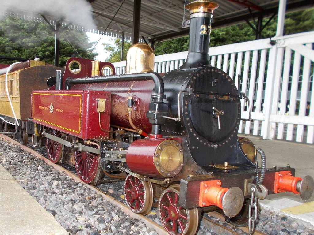
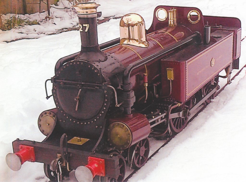
The next stage was to pump water into the boiler. The water level on the gauges was about 1/4" above the bottom nut. I tried the hand pump and was able to raise water in the gauge glass without difficulty. The next pump to try was the axle pump. I had designed and built the pump on similar lines to the one used on the Simplex locomotive. This is a double-acting pump with a bore of 3/4" the bore of the transfer passage is 7/32". I was at last able to test the safety valves and the blower. I opened the blower fully and the fire drew up rapidly. The steam pressure increased and as it approached 80lbs per square inch, I adjusted the valves to open at the correct pressure. A considerable amount of steam was released, so, I closed the blower and started to pump water into the boiler, which lowered the water temperature and the steam pressure was reduced. At first, the safety valves were slow to cut off, but this was later remedied by fitting stronger springs and increasing the clearance of the vertical rod in the safety valves, so they were able to move more easily. Lubrication of this engine is not easy, it is difficult by its design to reach all the moving parts. I have an oil can with a long spout, but this is a very hit and miss activity. I would like to have a system that is a little more accurate and to have less oil dripping to collect dust and grit. This first steaming was a success, and I was able to drop the fire with no difficulty. When the locomotive was completed it was dismantled for painting. Cleaning was carried out with cellulose thinners and a stiff brush to remove any debris. The brass was further treated with a light abrading with fine emery cloth and a further cleaning with cellulose thinners. All the steel parts to be painted were finished with three coats of acrylic based satin black. The brass parts and the wheels were finished in acrylic Vauxhall burgundy red, the nearest colour I could find to the Metropolitan colour. The paint was applied using spray cans. The lining and the lettering were transfers acquired from Kaylee Transfers and Precision Transfers. After applying the lettering and transfers, the boiler bands and the side tanks were given a thin coat of clear varnish by brush. The smokebox was finished in a matt black wood stove paint, again from a spray can. The locomotive was reassembled and another steaming took place. Unfortunately the acrylic paint on the boiler casing became very soft despite the insulation underneath. In fact when I wiped away some water from the casing I removed some of the acrylic paint, damaging the finish. Later I repaired the damage and gave the boiler casing a thin coat of clear varnish. Since this time the locomotive has been steamed many times; once at an all day event without mishaps, but the repair to the paintwork has not been completely satisfactory. The completed model of the Metropolitan tank locomotive
|
