Canvey Railway and Model Engineering Club.
CRAMEC signaling system replacement Above the old signalman's control panel Above, inside old signalman's control panel
The above photographs are of the old system being removed
The above photo shows the signalling systems taken off site for safe storage.
Old signalling system removed but pneumatics still to be removed.
Pneumatics removed; old signalling board reinstalled in new temporary location and in process of being wired into new distributor board.
Pneumatics are being reinstalled in their new location.
Old system reinstalled in new location.
Above photograph shows the new power distribution board (bottom left); And the new signalman's console is being made.
All the pieces of wood in the above photo are permanent and glued into position.
The above two photos show the removable sections that allow access to the wiring.
All the electronics sit on these plywood boards. The markings on the plywood board indicate the position of the electronic printed circuit boards.
The small box section is removable and gives access to the wiring harness.
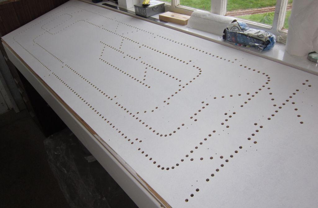
Displaying the signalman's control panel above. All the visible holes will have a red/green and blue LED's under the holes to indicate the condition of the route set. The points will have a red/green/blue and white LED's to indicate to the signalman the status of the points. The small pin holes are the position of switches. In operation the panel will operate similar to the NX style signalling systems of the 1980's. The signalman selects a route and then gives the signal; job done! The electronics do the rest.
The above photograph shows the reverse side of the signalman's control panel. The little black pillars are the base of the switches from the other side, and the white and silver bars of metal contain the LED strips. The pieces of paper that are glued to the board are to indicate where power supply rails are going, and where 40 way IDE connectors can be positioned. There are five hundred and ninety lights to be wired in; many on the same circuit fortunately; plus connections for the switches; hence why you see so many positions for IDE connectors.
The above photograph shows how the control boards will be inserted. Each board is 50mm by 150mm and there is a 10mm gap around each board to allow wiring to go under the board and then up to the signalman's display or down to pneumatics or to the main distribution board. Each function of the signalling system has been divided into individual boards so the whole system can be put together with a greater simplicity than normal. All of the boards run on a common bus structure. Looking at the top left board you will see the centre of the board has five terminals with two terminal blocks each side. The group of five terminals are used for all interlocking; block detection; signal operation, that includes home distant calling on and shunt; divisional block working normally called section release; and forward and reverse running. The outer two terminals each side of the main bus are for future expansion.
|