Canvey Railway and Model Engineering Club.
New Route Master Bus Competition.
These CAD drawings were produced by one of our members and entered into the Boris Johnson; Mayor of London New Route Master bus competition. The proposed bus can be powered by an on-board diesel engine, an overhead power supply, or battery. The configuration of the bus is easily changed by removing and inserting various modules into the side of the bus between the wheels.
In 2008 Boris Johnson announced the replacement of the old Routemaster bus. A competition was held for the design of a new bus; this was to be called a New Bus for London. A set of specifications were announced for the new bus; these stated the bus was to be two-man operated, have access for the disabled and a jump-on-and-off platform at the rear. For those of you that have seen the original specification and have also seen the bus that is now the so-called New Bus for London, or the New Routemaster as it is officially known, you will notice that the specification does not match the new bus. So for this reason we ask you, when viewing this proposed bus scheme, to consider this in mind.
A member of this club entered the competition with a bus like no other seen before. The strange wheel arrangement is to support a segmented pantograph at the top of the bus that picks up its supply from overhead power lines. These power supply lines do not have to be over the entire length of the journey, as the pantograph is able to detect the presence of the power lines and raise itself to engage the power to charge the onboard batteries that power the bus. This means that, at junctions, you do not have the complexity of overhead wires that you use to have with trolleybuses and trams. The pantograph detects the oncoming junction and lowers itself allowing the bus to run on batteries.
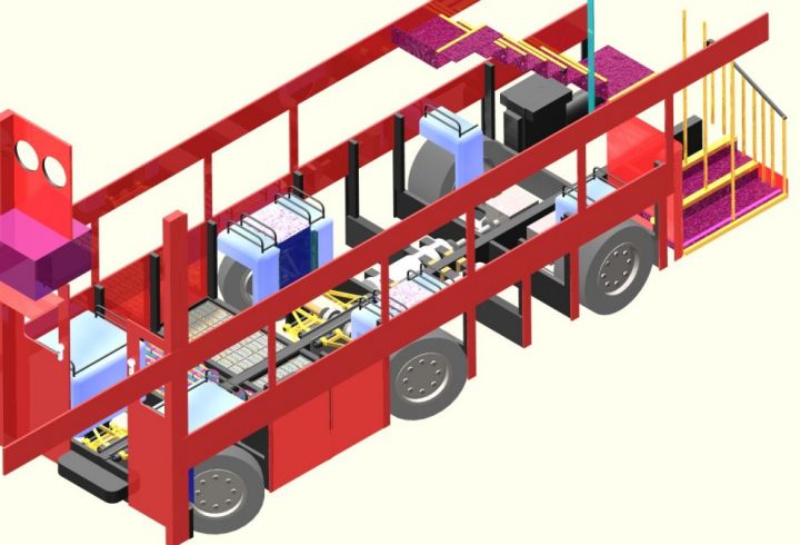
Looking at the picture below you will notice
that some of the contact wires are indicated as yellow and some are blue.
The blue wires are plain power supply lines, and the yellow wires are
power supply lines with a polarised radio signal imposed upon them.
Looking at the picture below shows the interaction between the power supply lines and the pantograph. Under each segment are rectified diodes; so whichever section of the pantograph is powered, the bus it is still able to be powered.
As you would expect with any electric vehicle, it has regenerative braking, which is achieved by charging a series of high-capacity capacitors. This saves battery life and is also more efficient. The batteries and the capacitors are inserted into the bus, through the side between the wheels, and are all connected to a common power supply system. So depending on the route chosen for the bus, and the availability of overhead power, these interchangeable power pods can be reconfigured for the best use of the route chosen. As these power pods are inserted into the side of the bus they can quickly be changed to either reconfigure the bus or change a defective power pod. In the event that the bus has to travel a long distance without overhead power there is a diesel generator under the staircase. To achieve the weight distribution for the batteries and the bus, the bus has a side chassis and a central structural member under the floor.
Future alterations.
|